A 111 Rehabilitation
The company Deutsche Einheit Fernstraßenplanungs- und -bau GmbH DEGES commissioned the Schüßler-Plan/VIC consortium with planning the rehabilitation of the A 111 motorway using BIM as the mandatory planning method.
The urban motorways to the west of Berlin are among those with the highest traffic load in Germany. The highway and structures date from the 1950s to the 1980s and are in great need of rehabilitation. The A 111 rehabilitation stretches from the Charlottenburg junction to the Berlin/Brandenburg state border. Besides these measures in the northern section of the motorway, work is underway on the A 100 in the southern section, such as the redesign of the Funkturm junction and the replacement of the Westenbrücke (bridge) and the Rudolf-Wissell-Brücke (bridge). One thing all the redevelopment measures have in common is that complex constraints posed by a highly dense, inner-city environment have to be taken into account when planning. In addition, the traffic restrictions during the construction period should be kept to a minimum due to the heavy traffic load. This article describes the digital pre-planning for the A 111 rehabilitation, represented by the use case "as-built model".
The Project in Detail
The A 111 federal motorway cuts through the north-western part of Berlin. It has a total length of about 13 km and was built in sections as a federal road between 1979 and 1987. It was gradually converted into a motorway in stages up to 2004. The plan aims to ensure the performance and safety of the A 111 with a time horizon of 50 years, during which only maintenance measures should be required. Over the course of the rehabilitation, the furniture and partly the drainage of the A 111 will also be renewed.
DEGES' Task, Targets and Specifications
The planning basis for the rehabilitation is DEGES' integrated traffic and construction concept which answers: "How can we build?", "What must be built?" and the combination "How can we get that done?" DEGES started by preparing the Employer’s Information Requirements (EIR) incl. the associated appendices. The EIR contains the information and specifications pertaining to the contractors' deliverables. In accordance with the BIM objectives, the next step was to create the model on the basis of the use cases and the requirements for the deliverables and model quality described in the EIR. The DEGES-CDE is a cooperation and coordination tool allowing joint processing and access to the same data for all employees (SSOT). Among other things, partial and specialised models are coordinated, checked and merged on a workflow basis. The card_1 Modelling Existing Conditions Module was used to create the as-built models. 3D surface models could be created once the specifications for DEGES' as-built models had been evaluated and constructively coordinated by all partners. Here it was necessary to clarify the following essential points regarding 3D models and to bring them into the context of the project requirements:
- Structure (specialised model/partial model/components)
- Geometry - Level of Geometry (LOG) (accuracy, segmentation)
- Attributes - Level of Information (LOI) (properties)
- Representation (material, colour)
- File naming (file naming convention)
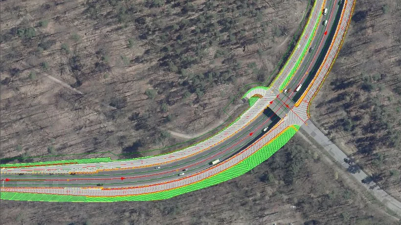
As-built Modelling Basis
The basis for the as-built modelling was primarily the survey data. This was determined via mobile laser scanning along the roadways and supplemented with tacheometric measurements. DTM data of break lines and topography was also imported into card_1, checked and structured. Special attention was paid to the streamlined modelling of the existing situation. The decisive factors here were consistent data, good data quality in terms of content and structure, and smooth data exchange via powerful interfaces with little loss of information. The as-built utility lines provided a further data source for the as-built modelling. This data was obtained via utility line probes and had to be partly remodelled from analogue documents. This resulted in considerable potential for the utility owners in terms of digital development, which had to be delivered in order to comply with the BIM method. This significantly increased the digital requirements demanded of the base data with regard to supporting further attribute and model-based processing. The data had to be available in very good quality in order to achieve a high degree of automation in the future and to reduce the - currently still high - proportion of manual preparation.
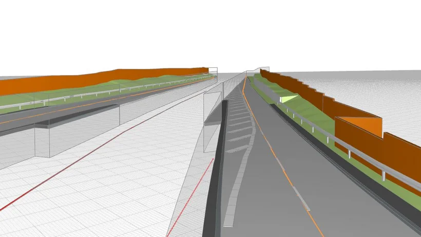
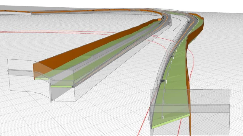
Creating the As-Built Model in card_1
The imported, further assessed topography and DTM data, prepared with every effort in a BIM-compatible manner, served as the source. For example, new layer structures, sewer lines, redefinitions of boundaries/parcels, codes and a higher number of auxiliary points for height fidelity were used. The processed source data was then successfully assessed. The model generation was carried out based on the code assignment and the component definitions defined in the Excel templates. The data was subsequently transferred to the coordination model and subjected to quality assurance.
Interfaces
Due to the high number of project participants, many individual subtasks arose within the project. The requirements for clearly defined interface management were therefore particularly high. They were defined in the coordination model by 2D spatial surfaces in addition to the 3D interfaces of the proprietary specialist models. Here it had already been shown that the division of tasks on the 3D model using the BIM working method was an improvement and helped to avoid collisions or errors.
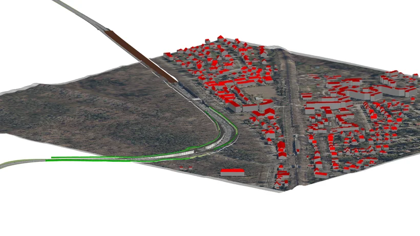
Creating the Coordination Model with DESITE
Basically, the as-built coordination model is where all the technical and partial models - required when planning the demolition, rehabilitation and new construction as well as planning the construction sequence and construction logistics - are brought together. This includes the existing traffic facilities including drainage, utilities inventory, bridge components, retaining walls, trough and tunnel components in the collision area of the route, third-party facilities in the area of influence, protected assets, the impact/"resistance" analyses and analyses from environment/nature planning as well as all relevant urban planning inventory data. In this project, the following models were integrated for the inventory:
- SM Surveying: digital terrain model with exchange format XML.
- ALKIS: environment models (LOD2) -data format CityGML
- Orthophotos: Source FIS-Broker Berlin -Data format Tiff
- SM traffic facility with furniture, drainage facilities and utility lines software application: card_1 - IFC/CPIXML as neutral data exchange
- SM civil engineering structures with bridges, retaining and noise protection walls as well as trough and tunnel structures in the conflict area with traffic facilities software application: Revit - IFC as neutral data exchange
In addition, the integration of the following models is planned:
- SM Environment
- SM Subsoil
Challenges
The basic rehabilitation of around 13 km of motorway in a complex inner-city environment not only places the highest demands on planning, but also on the technical implementation. The following points were given special consideration when planning:
- Coordination of internal and external performance limits
- Data preparation, modelling and quality assurance in consolidated models
- Compensation for missing interfaces and cross-software libraries, e.g. transfer of textured 3D symbols
- Multi-user problems with many sub-projects (data storage/ data management, up-to-dateness)
- Preparation, import and processing of GIS data
- 3D utility line modelling based on 2D plans
- Organisation of the filing structure and coordination of the file naming convention
- Number of models in the coordination model (performance, management)
Outlook
The next step is the "planning variant investigation" use case. The main objective here is to illustrate and optimise the construction process. The construction sequence includes, among other things, the construction conditions, the traffic routing during construction, the construction logistics, the deconstruction and the construction aids. The construction sequence is represented on the basis of the coordination model with a 4D navigator.
Contractor:
Schüßler-Plan
Grafenberger Allee 293
40237 Düsseldorf
Fon: +49 211 6102 01
E-Mail to Schüßler-Plan
www.schuessler-plan.de
VIC Planen und Beraten GmbH
Sauerbruchstraße 12
14482 Potsdam
Fon: +49 331 74960
E-Mail to VIC
www.vic-gmbh.de