CardScript for BIM Track Modelling
The BIM method is becoming increasingly important, yet challenges remain. 3D models with attributes are needed to work meaningfully with BIM without any loss of information. Manual procedures make updating arduous and difficult to manage. Integrated solutions must therefore be found that automate processes and work steps in order to manage large volumes of data. What could be more obvious than CardScript?
The BIM methodology contains many new features that are not yet uniformly defined: special cases in particular are often not covered and difficult to represent. Yet valid models are indispensable and form the basis of BIM projects. Without them, there is nothing for planners to discuss. The engineering office iproplan® Planungsgesellschaft mbH once faced such problems on a project for the Leipziger Verkehrsbetriebe (Leipzig public transport). In order to carry out the project in a BIM-compliant manner and be able to use proven software solutions, the planning office chose to employ CardScript.
A Workshop in Leipzig
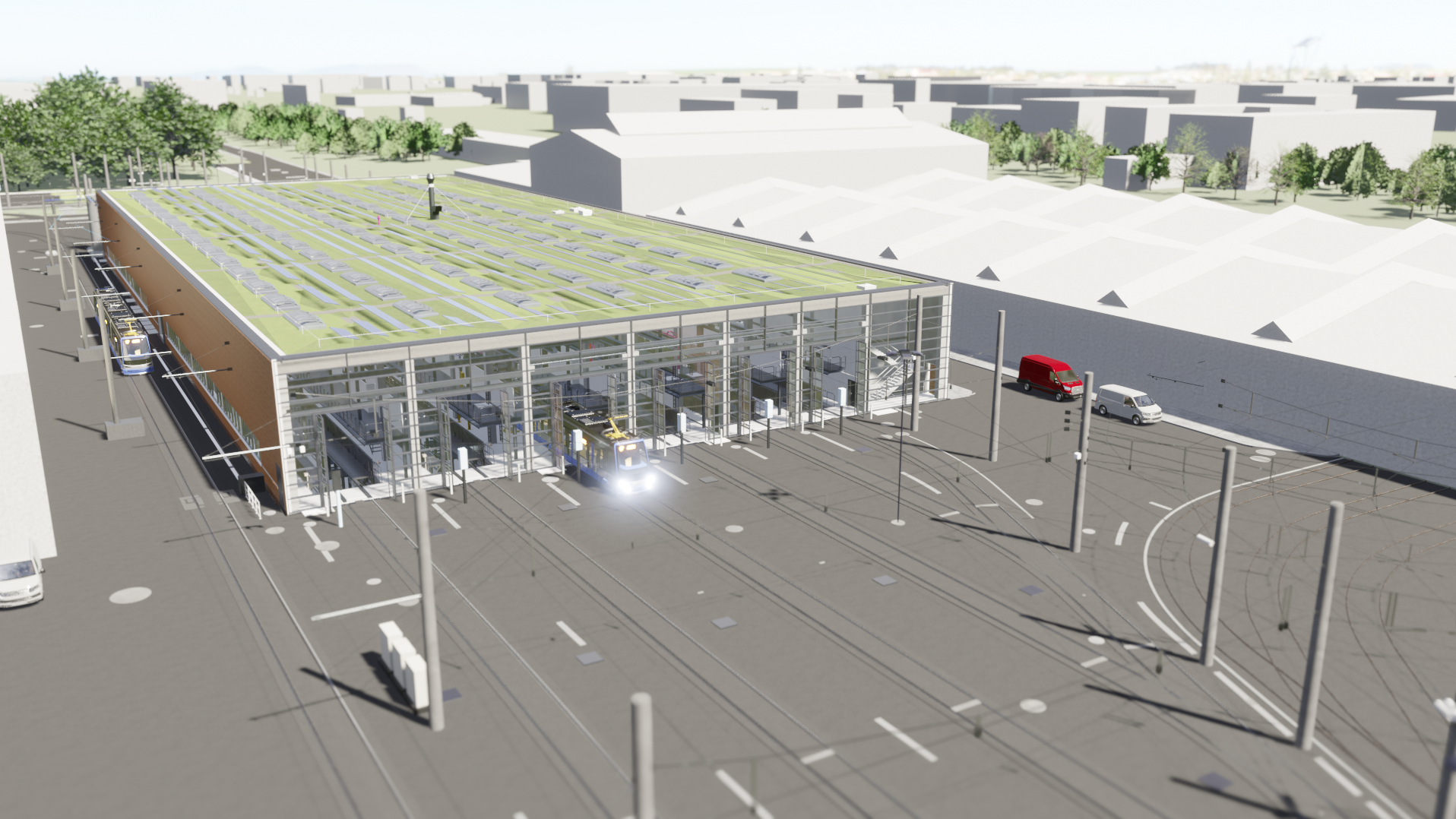
The Leipzig public transport company (LVB) is planning a new workshop at the Heiterblick depot for the maintenance and cleaning of its trams. With a total floor area of around 6,200m2, the building includes seven tracks with eight inspection pits and overhead work platforms providing areas for regular maintenance, cleaning and repair. In the outdoor areas there are tracks and switches serving the workshop, parking spaces for vehicles and a bogie warehouse. It was therefore important to coordinate existing and new lines in the designs. Various trades came together: architecture, building equipment, road construction, track construction, overhead line construction, safety technology, workshop equipment, signalling technology and line coordination. In order to better coordinate these trades, the client decided to use the BIM method on this project.
House Specialities
This project was challenging in more ways than one. Firstly, the BIM method requires valid models that contain appropriate 3D modelling and meaningful attributes. But the workshop is a building through which trains pass, resulting in a complex interface between the architecture and track construction. Manholes, reaches, tracks, sleepers, track fastenings, track beds, track coverings, special structures, kerbs, gutters and drainage all needed modelling. The specifics of this project made it impossible for us to use standard solutions in some places. Special cases are a big problem in 3D modelling.
The design team had to model selected track supports in the interior areas of the building where tracks with their attachments lay directly on the pit walls. There were also special superstructure shapes from existing modelling, for example the so-called “embedded tracks”. When attributing the models, the client had special requirements regarding the necessary attributes and their naming. All of these issues had to be solved, but we saw it not merely as a hurdle to be overcome, but also as an opportunity to use completely new technologies.
The Path to the Model is the Goal
How can such an opportunity be seized? As an engineering office, we had various options to choose from for this project:
- Remodelling using external software, which would have separated the modelling from the design.
- Switching to other software, which would also only cover standard cases.
- Developing our own solution using CardScript.
We chose the third option and bet on card_1. Using the system's own CardScript programming language, we developed a new software solution that combined tried-and-tested technologies with existing project data. It was important to us that we weren’t developing an isolated solution specifically for this project, but rather a scalable and reusable solution.
The early days of using CardScript focused on cross-section development, which used data from an Excel spreadsheet to create structures on multiple alignments and automatically attach attributes. Initially, the range of functions and the level of detail in the models were extremely limited.
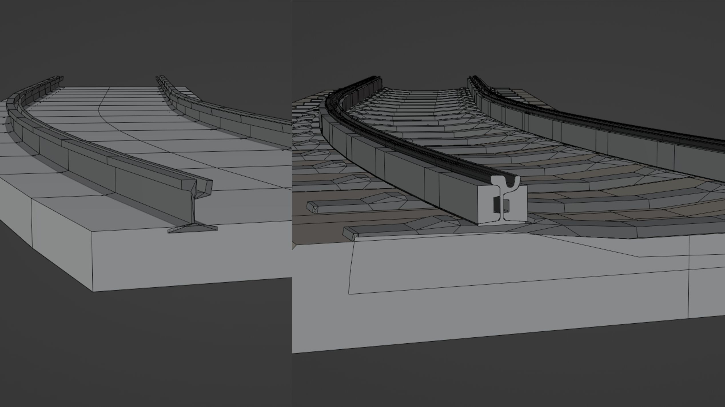
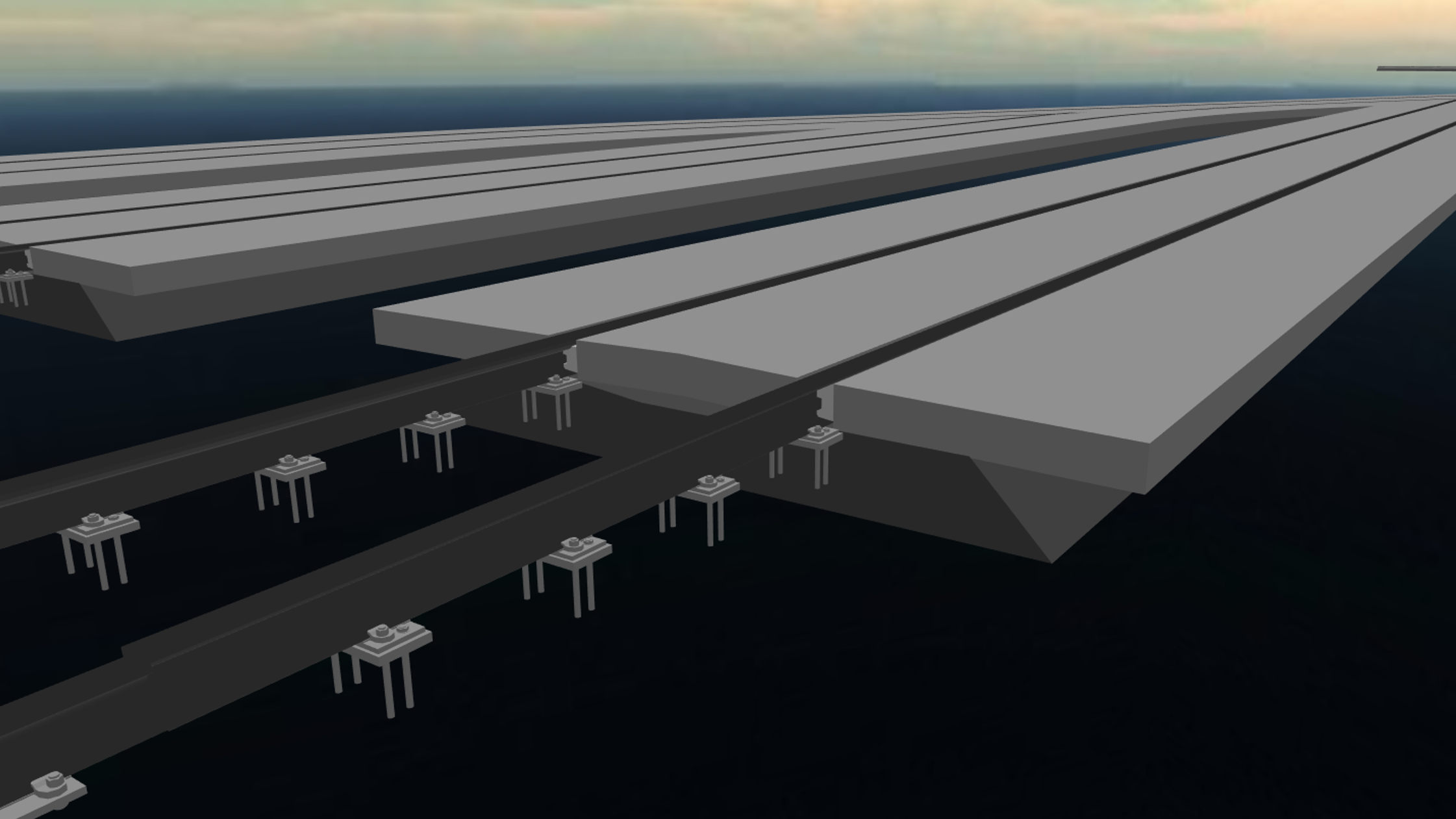
As our project planning progressed, the demands on detail and flexibility became greater. The first version did not meet these requirements, so we rebuilt it as an object-oriented system, thus simplifying maintenance and extensibility. This enabled us to create the models in greater detail and accuracy. It also improved coordination, because where initially only one track ‘floated’ through the building, the models of the actual track fastenings made it possible to detect conflicts with the structures in the ground.
The Right Tool For the Right Job
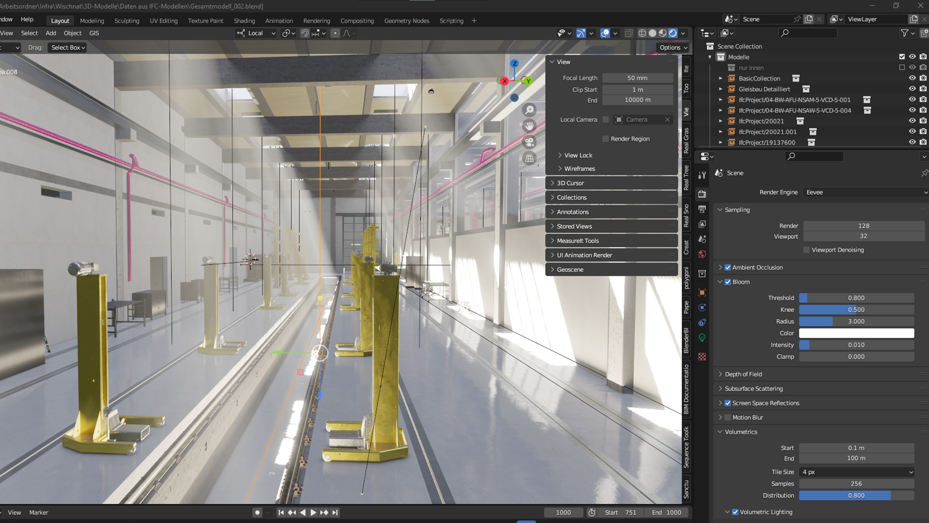
Although card_1 is highly specialized software that does an excellent job, it is not a 3D modelling tool. This required a different software solution that had a common interface with card_1. The choice fell to the open source software Blender, a 3D graphics suite. With the help of so-called “modifiers” and geometry nodes, the 3D geometries and 2D representations of the project could be created. These objects were read from a library into card_1 via a specially developed interface and inserted into the track model according to the specified parameters.
Improving Usability
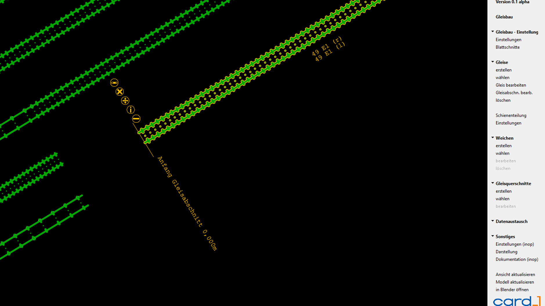
A text-based control was sufficient to start with. Then, as the project progressed, a graphical user interface with corresponding CAD menus and dialogues followed. This made it easier for other users to employ the solution. To provide direct visual feedback, all objects were displayed in the base map view where they could be selected and edited using active objects that perform functions when clicked.
We Have the Data – What Now?
Data is not collected for its own sake. The keyword here is use cases. One use of the data for the project was to automatically output structured quantities. For example, rail divisions were generated using a CardScript algorithm. For manholes, cut volumes were created using volumetric intersection with other excavated structures and the surface. Since 2D plans still play a major role in the infrastructure, we generated site plans from the platform and rail division data. Visualizing the project with the Blender software provided a very striking use case. The card_1 data exchange with Blender was achieved via the Python programming interface. As shown in the animation below the QR code, we added complex materials, reflections, animated vehicles and vegetation. This enabled us to supplement the track model with additional information and media.
All in All
BIM – meaning 3D, attributes, specialist semantics, data exchange, and above all teamwork and technology. As part of the project presented above, the project team had to master many challenges. This required a completely new set of tools, ones that leverage the classic and reliable foundations of the card_1 system and its script interface while allowing the user to create an attribute-enriched model with the required geometric detail. These tools can be further developed as desired and used for future projects. And though there are still a number of issues that need to be addressed, perhaps we should be talking about opportunities here?
Contractor:
iproplan® Planungsgesellschaft mbH
Beratende Ingenieure und Architekten
Bernhardstraße 68
09126 Chemnitz
E-Mail to iproplan
www.iproplan.de