What's New?
The new card_1 version 10.1 is a further development of version 10.0. It offers more key benefits, such as functionality, speed and comfort. We therefore recommend that you install the new version as soon as possible in order to benefit from these advantages.
See also
First of all, you will obtain an overview of the key features and enhancements of version 10.1:
-
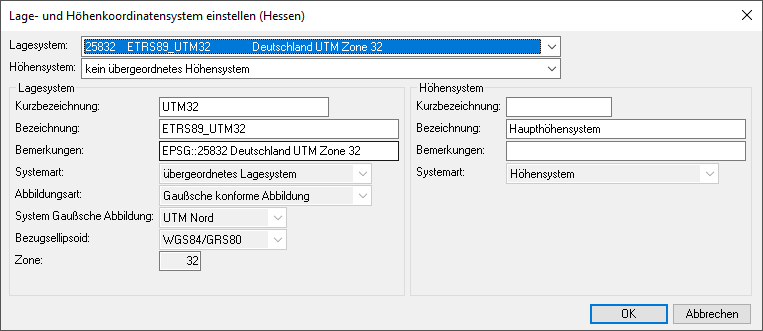
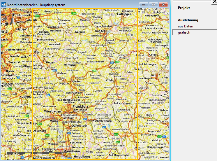
A Project Start Wizard facilitates the project start. When you create a new project, the programme offers the usual coordinate systems for selection, depending on the selected federal state (Project attribute Region). A background map will then be loaded, allowing you to define the required project extent.
-
Scrolling through the CAD menu with the mouse wheel has often been missed. This functionality has now been restored.
-
User-defined rules frameworks are now available for managing project-overlapping pre-assignments. Rules frameworks may be defined and combined in projects, for example in accordance with specific topics or clients. Rules frameworks can be easily and robustly maintained and provided, and transferred to multiple project areas. User-defined rules frameworks may be used to provide catalogue entries, drawings, drawing specifications and scripts.
-
In Version 10.1, raster images can be stored in external folders. This saves storage space, optimises backup and accelerates processing in network operation, if applicable.
-
Point clouds can now be imported in batch mode. The programme now also supports the compact, non-proprietary data format E57.
-
Topographic data may be marked using sub-attributes. This offers various possibilities for selecting data in accordance with specific tasks and for subsequent editing.
-
For road design purposes, the quick and simple generation of entrances and exits for rural roads and motorways in accordance with the valid guidelines will be available shortly. Complex structures such as traffic lane additions and subtractions or two-lane entries and exits are also supported. The result is a technical 3D model that can be easily checked and edited.
-
The construction kit Conkit can now be used to generate elongated components from individual cross-sections which can be stored in the component catalogue based on cross-section drawings. The component catalogue includes, for example, box drains, slotted and through channels, amphibian guidance systems, concrete crash barriers, and angled retaining walls.
-
The construction kit Conkit enables tangential connection of surface elements such as swales or trenches without a break (horizontal or vertical).
-
Data exchange between card_1 and DB-GIS/AVANI via GND-Edit was enhanced and optimised.
-
For the individual and subject-specific design of your models, it is helpful that you can import your own 3D symbols that you might have created using the free tools Tinkercad or Blender. The formats OBJ, FBX and GLTF/GLB are supported.
-
With the new possibility to export your data in XPlanGML file format, you meet the requirement of numerous public authorities to use the data standard XPlanung for exchanging urban land-use plans, spatial development plans and landscape plans.
-
The new Contact Catalogue may be used to manage project-related contact details for individuals and organisations, such as contact persons with clients, data providers, subcontractors, experts, etc.
-
The print system for lists via FastReport was updated and modernised. The previous FastReport component already used in card_1 since version 8.3 is now replaced by FastReport .NET.
Please read the following instructions carefully before installing card_1 Version 10.1.
|
Download Center |
You will find everything you need to install card_1 version 10.1 in the Download Centre of our website. Here you will find the installation package, the installation guide and additional sample or template projects. You can also order your personal licence data here which you will need for the installation. |
|
System Requirements |
Here you find a complete overview of the system requirements of card_1 version 10.1. |
|
Project Backup |
First of all, we would like to reemphasize the importance of project data backup. Your project data is extremely valuable. A loss of data may cause significant workload and cost, which can be avoided easily. Therefore, it is in your own interest to check when you have saved your card_1 projects for the last time. NOTE We recommend that you save your project data before the installation of version 10.1. |
|
Parallel Installation |
The installation process of version 10.1 will run in parallel to a possibly existing card_1 version 10.0. Both card_1 versions may work in parallel. However, please note that the data of version 10.1 are not backward compatible and can therefore no longer be edited using version 10.0. |
|
Project Conversion |
NOTE Please note that projects that have been converted for card_1 version 10.1 can no longer be edited using older card_1 versions (no backward compatibility). Your project data in card_1 version 10.1 can only be converted for projects from data version 8.4.0.0. Older projects (not older than version 7.7) must be previously converted using card_1 version 8.4. Standalone converters are available for projects that are older than version 7.7. Our recommendation: Please bring any older projects to data version 8.4.x.x using card_1 version 8.4, at the latest before permanently uninstalling card_1 8.4. Otherwise, keep version 8.4 working on at least one of your workstations for subsequent conversion. This also requires Firebird version 2.5 to be installed. |
|
Print Layouts |
The list print system was updated: The proven FastReport component was replaced by FastReport .NET. Print layouts (*.fr3) created using the previous component are not compatible with the new system and cannot be converted. Use the function New Layout in the menu Settings > Print Output > Edit Print Layout Headers in order to create the print layout header of your company. |
First of all, a short review of significant enhancements we have already made available with the ten freshups of the previous version 10.0.
|
Surveying and Topography |
|
|
Road Design |
|
|
3D Design Elements Surface |
|
|
Rail Surveying, Design |
|
|
Water Management Classic |
|
|
Catalogues |
|
|
Project Backup |
|
In this section, we would like to draw your attention to our new card_1 modules. If you are interested in the new card_1 modules, please contact your local card_1 sales partner.
|
Cross-section Design / 3D Route BodyBIM |
Besides the traditional cross-section design, this module for version 10.1 comprises a basic package of both the New Road Design and the Construction kit ConKit. This includes, for example, the creation of rural roads, motorways, pedestrian and bicycle lanes, the definition of traffic lanes and carriageway geometry, the generation of the route body including carriageway markings and entrances. In addition, it includes design elements from the Construction kit ConKit, such as kerb, wall, shoulder, swale, slopes, ground connection, connection strips, remaining areas, etc. In contrast, junctions, signs and parts of structures are not included. |
|
3D Road DesignBIM |
The module should licence all functions and types, which fall into the application field Road Design and are not part of the module Cross-section Design / 3D Route BodyBIM. Compliant automated design of junctions, t-junctions, corresponding junctions, ramps, entrances and exits. The module will be extended step by step to include bifurcations (for interchanges), roundabouts, service roads, ancillary facilities, etc. |
|
3D Design ElementsBIM |
Based on the Construction kit ConKit, this module should enable interactive subject-specific design of, for example, lateral clearances of railway and road routes, squares, entrances and traffic areas of private and commercial properties as well as terrain surfaces. Alignments, topographic lines and terrain models are required for the design, according to the situation. |
|
Issue ManagementBIM |
Use the Issue Management in card_1 to document and manage tasks, problems and any other information, which shall be processed at a later project stage and, if appropriate, shared with colleagues. However, issues are not only text information. An important characteristic of issues is that fact that they may be located in your project. This means that issues have a 2D or 3D reference in your project model, with the advantage that, when you read the problem description, you will simultaneously see the problem in both the base map and the 3D project view. The BCF interface is available for exchanging your issues with external project participants. This way, the tasks and messages managed in the issues can be easily handled jointly. The Issue Management in card_1 is helpful for both the self-organisation and the communication between the users involved in a card_1 project or for the communication with external project partners. |
|
Central Project Files |
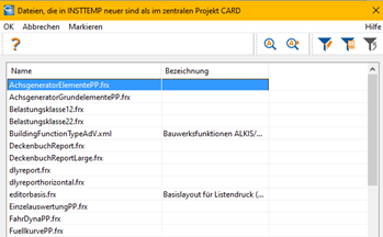
During a card_1 freshup, the update process also refers to central project files. When you first open a project after a freshup, you will receive a log message to say that the files in the central project should be checked. When you later open the central project, the programme will list the updated files. Mark the files which should be replaced by newer file versions.
NOTE There are project files which are exclusively maintained by IB&T and will automatically be overwritten during a freshup with project conversion. These files shouldn't be adjusted but adopted during the freshup. |
|
Graphics engine for 3D project view |
card_1 version 10.1 now uses version 2.2 of the graphics engine Ogre-Next. In addition to general bug fixes and performance improvements, it offers a new method for managing textures. All textures, e.g. in 3D symbols, are now reloaded when necessary and asynchronously. This may significantly shorten the time until the project is started and 3D symbols are displayed. |
|
Print System for Lists |
The print system for lists via FastReport was updated and modernised. The previous FastReport component already used in card_1 since its version 8.3 is now replaced by FastReport .NET. The new component offers reliable processing routines and a modern user interface, which makes the process of designing your outputs easier and more intuitive. In addition, you benefit from current outputs using standard file formats and a simplified installation. |
|
Contacts |
In version 10.1, contact details of individuals and companies extend the card_1 data model. Use the contact catalogue to manage contact details of clients, data providers, subcontractors, BIM coordinators, etc. (see Contact Catalogue). |
|
Toolbars |
Optimisation of object update: Control options for updating objects are especially intended to facilitate the handling of technical objects. Object update may be temporarily disabled, which enables consecutive changes of parameters to be carried out faster. However, in view of numerous interdependencies between the objects, it is important that a current and valid state is regularly reproduced. This is why the object update rules have been revised.
|
|
Scroll through CAD menu |
With Windows 10, Microsoft has created the possibility to 'scroll through inactive windows while pointing' in the mouse settings. Enabling this option causes a change in the flow of messages: The card_1 frame window with docked CAD menu no longer receives mouse wheel messages from the operating system, when the mouse is positioned in the CAD menu. With version 10.1 it is again possible to scroll through the CAD menu with the mouse wheel. |
|
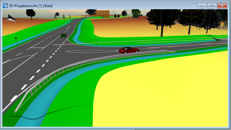
3D Project View |
Faster working: Due to the transition to the new version of Orgre-Next and the support of asynchronous loading of textures, the 3D project model is available more quickly for further processing. |
|
3D Project View |
Lines: Due to the transition to the new version of Orgre-Next, the limitation of the line points to be displayed was abandoned. |
|
3D Project View |
Virtual Reality: The Virtual Reality was improved based on the new version of Orgre-Next.
|
|
Base Map View |
Background map: Background maps can be displayed not only in their original appearance but also modified, e.g. pale or in grey scales. Thereby, the download and storage of raster images becomes obsolete for some application cases. This saves time and storage space. |
|
Base Map View |
Raster images: Raster images, which are only intended to be displayed, can be stored in external folders, especially in order to save storage space and to accelerate project backup.
|
|
User-defined Rules Frameworks |
With card_1 version 10.1, you can combine pre-assignments across projects in your own rules frameworks.
|
|
3D Symbol Catalogue |
With the Visualisation module, you now have the possibility to use your own 3D symbols. Use free tools, such as Tinkercad or Blender, to create your own 3D models (textured, if desired) and import them in the 3D symbol catalogue. Supported 3D model formats for import include OBJ, FBX and GLTF/GLB. As a next step, you can define the insertion position, the orientation and the scaling for the 3D symbols. By analogy with the 3D symbols, which we make available to you as a rules framework, you may use your own 3D symbols for editing and design of your project models. |
|
The component catalogue now enables the definition of multiple components in one cross-section (Multi Cross-sections). Use the catalogue to store corresponding cross-section drawings. Components may be assigned a material. This way, it is possible to generate elongated objects along tracking paths. The rules framework 'Basis_Strasse' was extended to include components for box drains, slotted and through channels, amphibian guidance systems, concrete crash barriers, and angled retaining walls. |
|
|
The new contact catalogue in card_1 version 10.1 enables you to manage your project-related contacts.
|
|
|
Sub-attribute definitions for DB GIS have been revised for purposes of DB InfraGO:
|
|
|
Sub-attribute Assignments |
Sub-attributes can now be specifically assigned to subordinate alignment types. This way, each alignment may be assigned user-defined attributes and pre-settings differentiated according to the code, type or subtype. |
|
Surveying Settings |
Distance reductions due to elevation and projection for primary coordinate systems are now preset for preparing the measured data. |
|
New Project |
Project Start Wizard: Use the new wizard for a more comfortable entry into new projects.
|
|
New Project |
Now, an unregistered project no longer prevents the creation of a new project with the same name. A message will now be displayed to say that the folder already exists. |
|
Backup |
Email configuration file, new parameter 'Cc': This enables you to specify the email address of the recipient of a copy. |
|
Backup |
The programme now checks whether the versions of the files cardbackup.jar and export.jar are identical. If this is not the case, the backup will be cancelled and a corresponding message will be output in the log. Copy the mismatching jar file from the card_1 programme folder to your backup programme folder. |
|
Manage Point Clouds |
New import format E57: The import was extended to include the compact, non-proprietary data format E57. |
|
Manage Point Clouds |
New Batch Import Function: The multiple file selection can now be used to import multiple point clouds in the formats LAS/LAZ and E57 in a single working step. For example, public authorities provide comprehensive laser scan data as a basis for your transport infrastructure planning. Since point clouds are provided in tiles, your project area may comprise a large number of files. |
|
Mark Topography |
Mark using Attributes: The function groups for editing topography have been extended to include a marking option using sub- and object attributes. In this process, you may also use multiple attributes for marking purposes. Example: Mark all lines of the current layer, which have the entry 'Elektro' in the sub-attribute field 'Branche>Thema', whose value in the sub-attribute field 'kV' exceeds 110 and whose 2D line length exceeds 1 m. |
|
Evaluate Topography GIS |
GIS evaluation functions, such as the creation of drawings from sub-attributes or the generation of area signatures within circumference lines, can now be accessed directly via topography editing, if GIS Import or GIS Export is licenced. This way, the detour leading to these functions within GIS data exchange becomes obsolete. |
|
Generate Structures (Topography) |
Function Structures made of Lines - Crash Barrier: If the traffic barrier includes a lowering, it will now be generated within the topographic line.
|
|
Design Road |
Simple generation of entrances and exits: The new card_1 version 10.1 enables quick and simple generation of entrances and exits for rural roads and motorways in accordance with the valid guidelines. Complex structures such as traffic lane additions and subtractions or two-lane entries and exits are also supported. The result is a technical 3D model that can be easily checked and edited. As a first step, design the horizontal and vertical alignment of a connecting ramp. Based on this, generate the route body of the ramp. card_1 automatically recognises whether the ramp is part of an entrance or an exit and generates the entry and exit lane as well as the transition segments to the ramp. The cross-fall of the entry and exit lane can be adjusted individually. It is also possible to select the types designated in the guidelines, including traffic lane additions and subtractions or two-lane entries and exits. Technically correct solutions for traffic lane and hardstrip widenings will also be found in this process. Thanks to the simplicity of the generation process, you can check quickly whether the entrances and exits are feasible in the particular situation in terms of space and vertical profile. The generated 3D model is an ideal basis for visual examination. In addition, the programme will check the carriageway geometry for zones with poor drainage. The results will be output in the journal system and zones with poor drainage will be displayed in the graphics. All parameters, such as the length and width of entry and exit lanes, can be modified at any time. The new result will be generated with a single click. |
|
3D Design Elements Equipment / Surface |
Components from individual cross-sections: It is now possible to generate elongated components with individual cross-sections, e.g. concrete crash barriers, other walls or draining channels, and angled retaining walls. Cross-sections can be selected from the component catalogue. The catalogue may also contain user-defined cross-sections based on drawings or multi cross-sections (see Component Catalogue).
|
|
3D Design Elements Surface |
Clamped Elements: So-called clamped elements are now available to ensure a simple and elegant interconnection of surface elements, e.g for tracking paths, swales and trenches. These clamped elements enable smooth interconnections between the selected connecting objects. For this purpose, the programme automatically generates a spline which connects tangentially to the existing elements both horizontally and vertically. |
|
Manage Alignment |
Alignment Attributes - Subtype: The subtype of an alignment is already selected in the first dialogue box along with the alignment type. The alignment attributes matching the respective subtype will be automatically pre-assigned. For example, the type 'Railway - Track Opposite Designated Direction' will be automatically assigned the direction code 2. |
|
Manage Alignment |
Alignment Attributes - Alignment Type 'Railway': Now, the subtypes 'Track Alignment' and 'Chainage Line' have different dialogue boxes for entering parameters. Additional sub-attribute definitions have been created for the GND-Edit interface (see also Sub-attribute definitions). In the GND specifications, track alignments and chainage lines have different sub-attributes. For example, a track alignment has the sub-attribute 'Track Type' for aboveground and inoperative railway lines or station tracks. In contrast, a chainage line has the sub-attribute 'Chainage Line Type' for left, right or all tracks. |
|
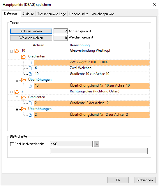
Prepare DBAG Points |
Functions Save Points Single and Save Points Multiple:
|
|
Prepare DBAG Points |
Function Change Attributes: Due to the changes made to sub-attribute definitions for GND (see also Sub-attribute Definitions), the dialogue box for checking and changing attributes has been adjusted accordingly.
|
With regard to Water Management Pro, our development partner aRES actively works on a regular basis to incorporate improvements and innovations.
|
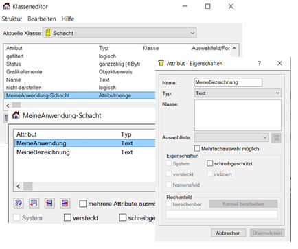
Probably available with version 10.102 |
The Class Editor for Sewer Objects in Water Management Pro enables you to define and manage your own attributes. This can be helpful, for example, for the assignment of attributes according to client information requests (Auftraggeber-Informationsanforderungen, AIA) and for the assignment of services according to the standard services catalogue (FitMatchKey).
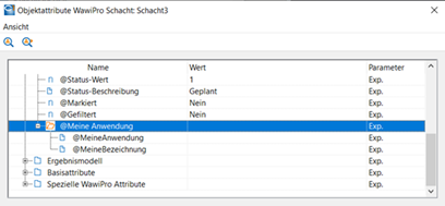
These are now also available for the resulting technical objects in card_1 for further use and especially for transfer in the IFC or CPIXML format. In the case of changes or extensions to Water Management Pro, the attributes will be updated when new technical objects are generated.
|
|
Create Raster Drawing |
Drawings from Background Maps: Now, raster drawings can also be derived from background maps. The drawing to be created is based on the currently set background map. The level of detail of the resulting drawing can be controlled through the selected pixel spacing. Consequently, it is no longer necessary to save raster images before using them in drawings. |
|
Create Drawing |
Insertion files and drawing objects can now be selected from an activated user-defined rules framework.
|
|
Import/Export GND-Edit |
Function Import Point Codes: The point code assignment was enhanced. The points are now considered separately according to topics. The dialogue box contains multiple tabs with different topics:
|
|
Import/Export GND-Edit |
Function Import MDB:
|
|
Import/Export GND-Edit data |
Functions Export MDB-DBGIS/MDB-AVANI: The selection of the data to be exported is clearly arranged and simpler. In addition to the alignments, alignment-independent points and cross-track distances are also output. |
|
Export GIS Data |
New Export Format XPlan: GIS export was extended in order to cover the possibility of exporting data in XPlan format. This format is used to exchange urban land-use plans, spatial development plans and landscape plans. Many public authorities require the use of XPlan format or have planned its mandatory introduction. Since card_1 supports this standard, you can use card_1 to carry out all your measurement or design processes in these fields and deliver results which comply with the applicable regulations. |