BIM in Road Planning
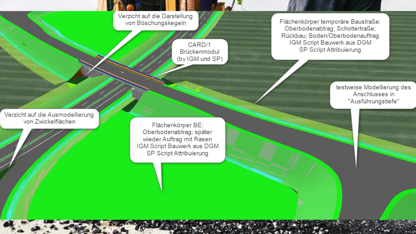
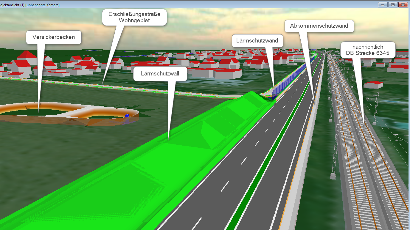
In a BMVI pilot project directed by DEGES, the preliminary planning phase of a 14.0 km long section of the B87 between Eilenburg and Mockrehna is being examined using BIM. The engineering company Schüßler-Plan is contributing directly to the testing and development of the BIM method in this pilot project. IB&T is supporting Schüßler-Plan as a development partner.
The B87 highway runs from the A38 at Lützen-Süd in Saxony to Frankfurt (Oder) in Bandenburg. The Federal Highways requirement plan includes the sections from Leipzig to Eilenburg, from Eilenburg west to Torgau (existing design section), the local Torgau bypass and a section east of Torgau for the state of Saxony (Federal Transport Infrastructure Plan 2030). These sections principally serve to link the middle hubs of Eilenburg and Torgau to the upper hub of Leipzig. The B87 is therefore one of the most important arteries of regional and state development in northern Saxony.
Base Data in 3D
Designing with BIM requires a completely new approach to plotting routes. Whereas traditional designs involve searching for corridors with a low space impact on 2D maps in the base map then viewing them in the drawings, with the BIM method, everything is 3D right from the start. It is now the model, rather than the base map plus elevation plan, which forms the basis of designs. From the surveying data a DTM is generated into which all further information such as land utilization, conduits and environmental considerations are to be integrated. This model of existing conditions then forms the 3D basis for the route design. When creating the model of existing conditions, the pre-processing of the existing conduits was particularly challenging as these generally have not been previously surveyed. The base data obtained were mainly 2D drawings in the DWG and DXF formats. It quickly became clear that a certain amount of effort was required in order to generate data suitable for BIM.
Generating Data suitable for BIM
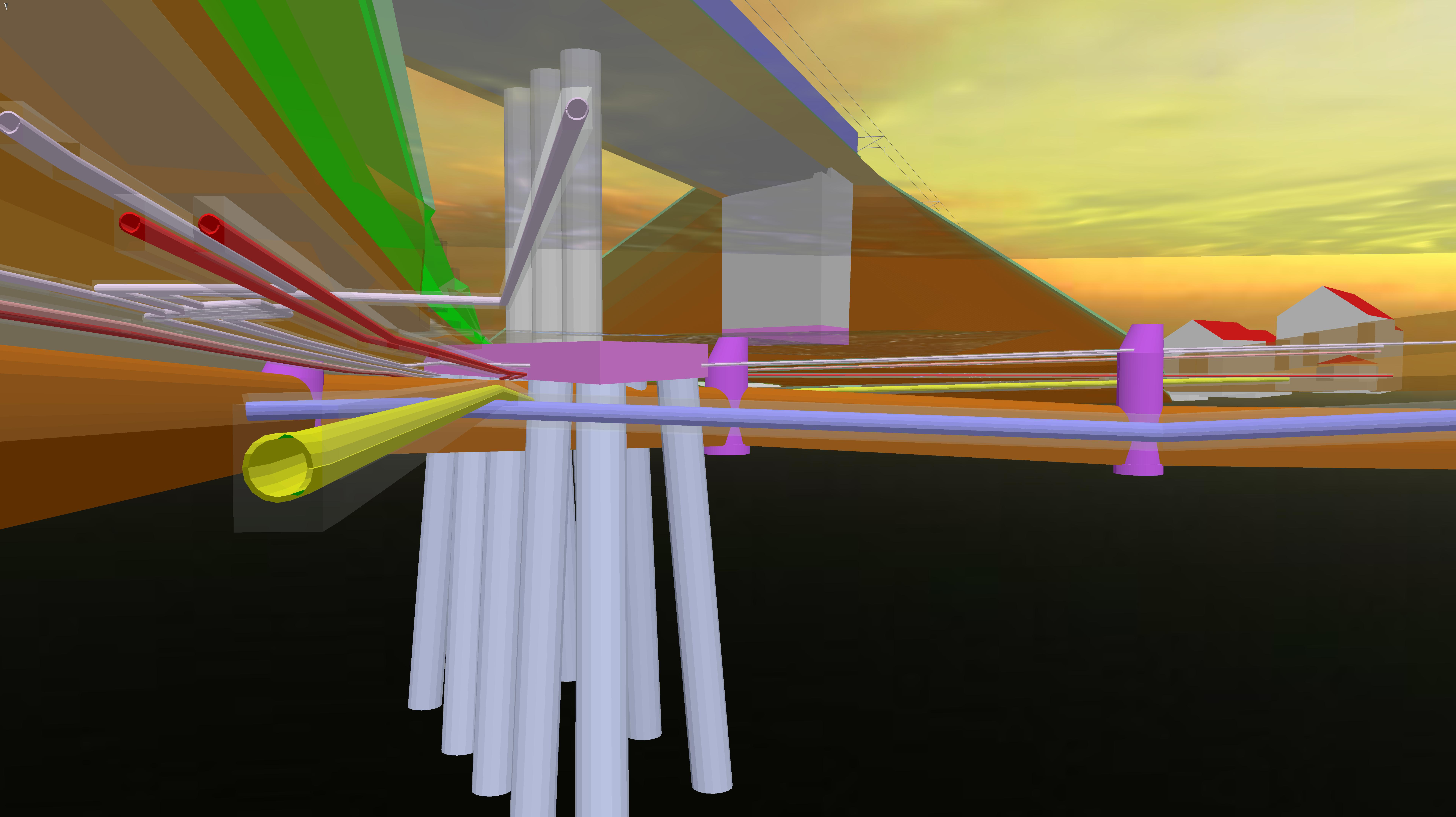
card_1 provides a versatile tool with which we can tackle this task. At the time, card_1 already had a conduit generator, albeit without the "transparent structure function" and attribution capability. A quick solution was found using CardScript. Using dialogue-based functions, all 2D conduit lines could be allocated DTMs, cover heights, nominal widths and safety clearances (3D transparent structures) needed for 3D modelling (see image 2). Furthermore, all important information was automatically supplied to the 3D conduits as attributes. card_1's Conduit Generator now produces the components' safety clearance and attribution in a BIM-like manner.
Requirements – EIR (Employer’s Information Requirements)
In the EIR the client stipulates the requirements placed on the project's models, the definition of design goals, determination of the level of design accuracy, the deliverables and work processes. Among other things, the EIR contains:
- BIM project goals and BIM application cases
- technical requirements on software, data exchange and data transfer formats, data exchange system (CDE - Common Data Environment), modelling regulations, precision and design level of development (LoD), section allocation, file naming conventions, coordinate systems, employer's starting data plus statements on 3D (as-is and plan), 4D (time and program), 5D (costs) and 6D (lifecycle considerations).
- Management requirements such as responsibility and performance indicators, BIM-Execution Planning (BEP) requirements, the collaboration process, quality assurance, plausibility and check tests, data security as well as norms and guidelines.
Based on these requirements, the "script" for the planning process is worked out between the design team and the client: the so-called BIM-Execution Planning (BEP).
Project Handling – BEP
As part of the tender process, the client has already delivered a detailed EIR in order to gain a draft BEP to then consult when preparing the bid. Designing is no static event, however: it is a dynamic process, so the BEP be constantly compared to the project requirements and where necessary updated.
Open BIM
When generating the design model up to a 6D depth, i.e. 5D plus lifecycle considerations, the use of different types of software is required. Depending on the design phase, the emphasis is on CAD routing software, software for the tender and contracting process or project management software. In this case, the routing software VIS-All® 3D of the software service John was used for the preliminary route design and card_1 used for the detail planning. Creating the combined trades' composite model including conflict detection and coordination was done by thinkproject's BIM-analysis software DESITE BIM md, which can be linked to tender/contracting software e.g. (iTWO from RIB or MS-Project management software). Due to the pilot-project-nature of the designs, it is necessary to adjust the software constantly in order to map previously unknown applications adequately and solve interface problems. Schüßler-Plan is naturally in close contact with the software producers.
Conflict Detection
An integral part of the BIM method is the automated detection of conflicts in the 3D model. The aim is a systematic, virtually complete removal of design conflicts or contradictions. To this end, the 3D models of every discipline are brought together into one consolidated, multi-discipline coordination model. When designing roads, variations must be investigated and compared in the initial stages of BIM design. A variation model derived from the various disciplines in conjunction with route variations was therefore generated. It quickly became apparent, however, that such 3D models generate huge volumes of data while placing increasingly high demands on the hardware. Once an automated analysis of the consolidated coordination model or variation model is carried out according to defined rules, geometric problems can be identified schematically through the software. It was also clear that it is useful to model more 3D objects than what the design phase would initially seem to require. The reason for this is that the information may contain a lower level of precision than is necessary. A classic example is the display of existing conduits. The pre-processed conduit data mostly shows only a relatively inexact geographic position. If the conflict detection with its 3D structure of the conduits model were compared against the designs, misinterpretations would likely occur. An observer might also conclude that the conduits' position is realistically displayed. This, then, is the reason for the additional "transparent structure", modelled around the conduits as an area of uncertainty (see image 2). When running the conflict detection, this serves to identify areas of risk which should then be investigated more closely in the later design phases.
Automation
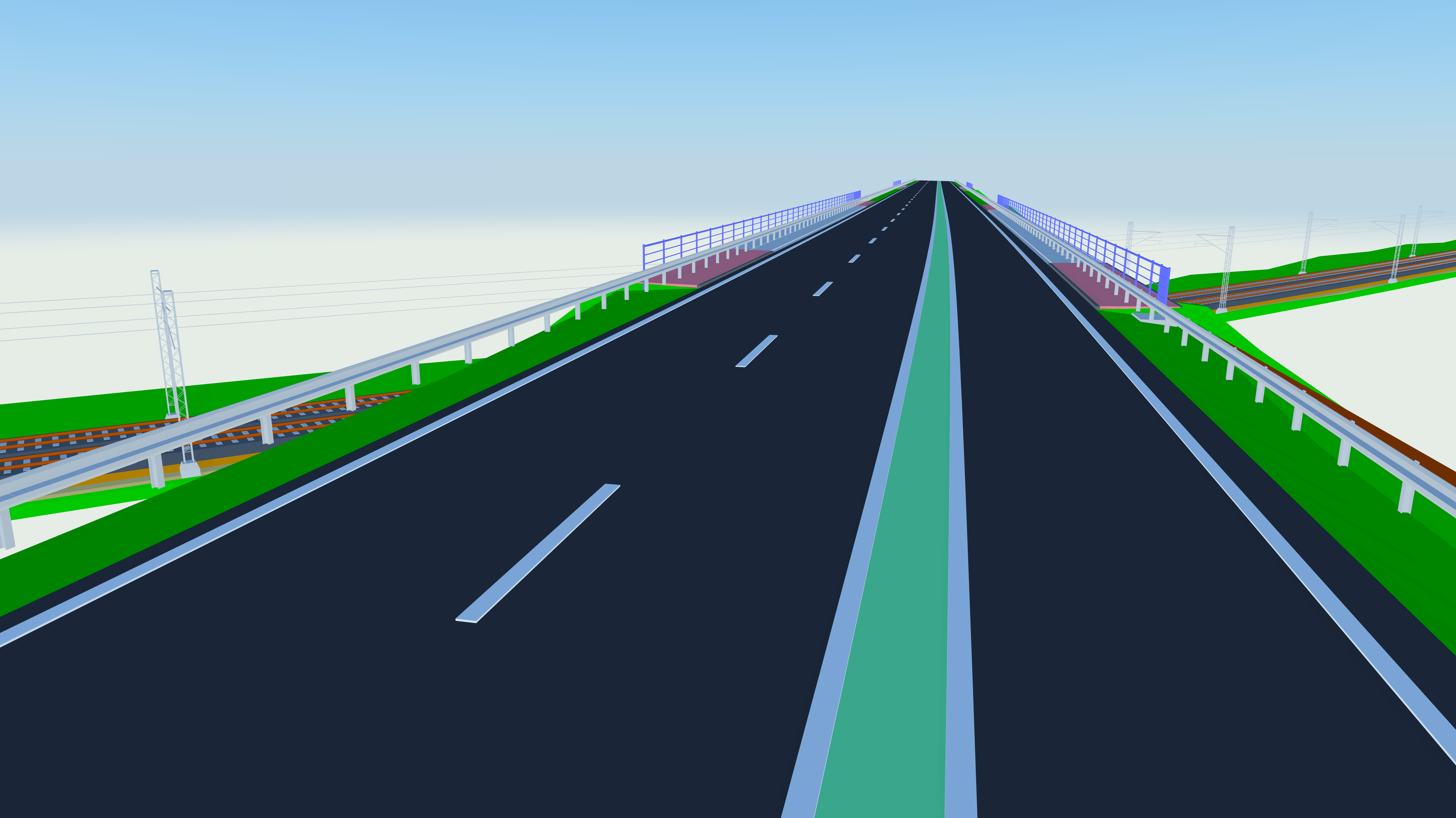
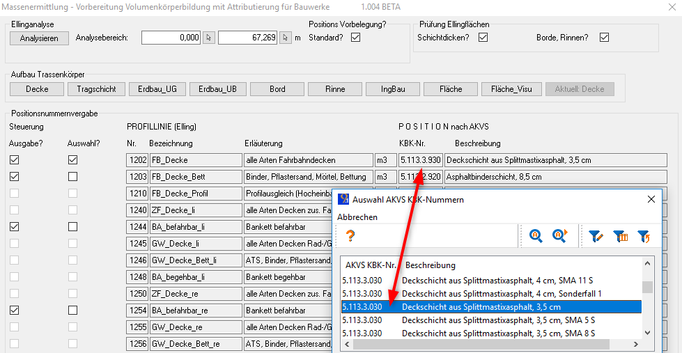
A further aim of the BIM method is to automate, as far as possible, the processes in order to avoid losses or errors between interfaces. During the conventional planning phases, information is always exchanged among the various fields involved. These include planners in areas such as surveying, the environment, noise, engineering structures and soil analyses. So too is the planning status quo exchanged among traffic planners when calculating quantities and costs. Besides geometric 3D structures, attributes must also be exchanged and evaluated. Right from the start card_1 allowed us to use our cross-section calculations, including attributable 3D structures. Thanks to the close partnership with IB&T, our system, initially only semi-automated, could become a fully-automated one. That means that the key attributes contained in a database could be allocated directly when designing cross-sections (see image 3). The pre-assignment was selected in such a way that in most cases only the pavement structure need be adjusted via dialogues. For more specialized structures we apply our own analysis tools developed using CardScript; tools which make a first sampling in card_1 possible both before and after generating the 3D structures (see image 4).
Coordination Model
The individual route structures were exported to DESITE MD via CPIXML. We decided on the "Route Section" method so that should there be any changes, it would not be necessary to export the entire route structures to DESITE MD's design model. This allows for later 'surgical interventions' in the coordination model. IB&T provided us with a batch export to transmit the route sections. Only this made it possible for us to analyse 21 variations and finally select 4 variations for the preliminary assessment within the given time period. More than approx. 3 million 3D objects would ultimately be needed to adequately model all variations. A modular approach was the only way to significantly reduce the number of 3D structures so that a useful coordination/complete model could be generated with approx. 300,000 objects.
Evaluating Quantities
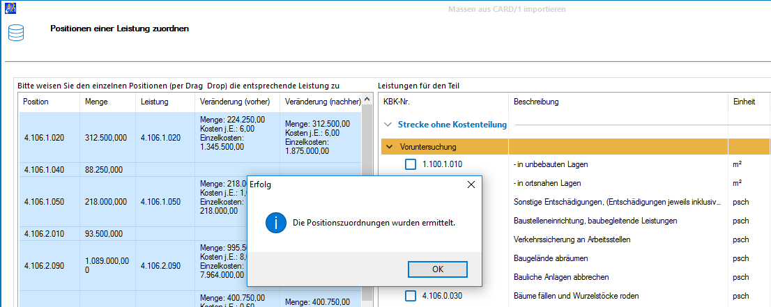
In order to round off the workflow, we developed our own menus for calculating volumes via DESITE MD. Just one click allowed us to export quantity evaluations based on different variations to the card_1 Cost Calculation AKVS/elKe programme. Here the quantities are automatically assigned a KBK number, which significantly cuts down on the workload involved in producing the 4 cost estimates required by AKVS (see image 5). This also serves to virtually eliminate manual transfer errors.
In Short
Many questions remain unanswered. The efforts of politicians and business leaders would indicate that the BIM-based planning process will take hold and in future be used as the definitive method. It offers planners more room to manoeuvre when examining details and leads to a clear improvement in the quality of designs and documentation. This can only be a huge plus for the entire planning process.

