Warsaw North Bridge
In June 2007, the engineering company Schüßler-Plan was put in charge of planning the North Bridge "Trasa Mostu Pólnocnego". It was to be completed within 282 days. The Polish capital is developing into an important and thriving Central European metropolis. Traffic around Warsaw is expected to increase significantly within the next 30 years, stretching Warsaw’s main traffic network with its radial layout beyond its limits.
A link road will bring much needed relief: The 3.4km section being designed starts at the Pulkowa arterial road junction to the west of the Vistula and joins it up to the Modlinska arterial road to the east of the Vistula.

The 3.4km centre piece
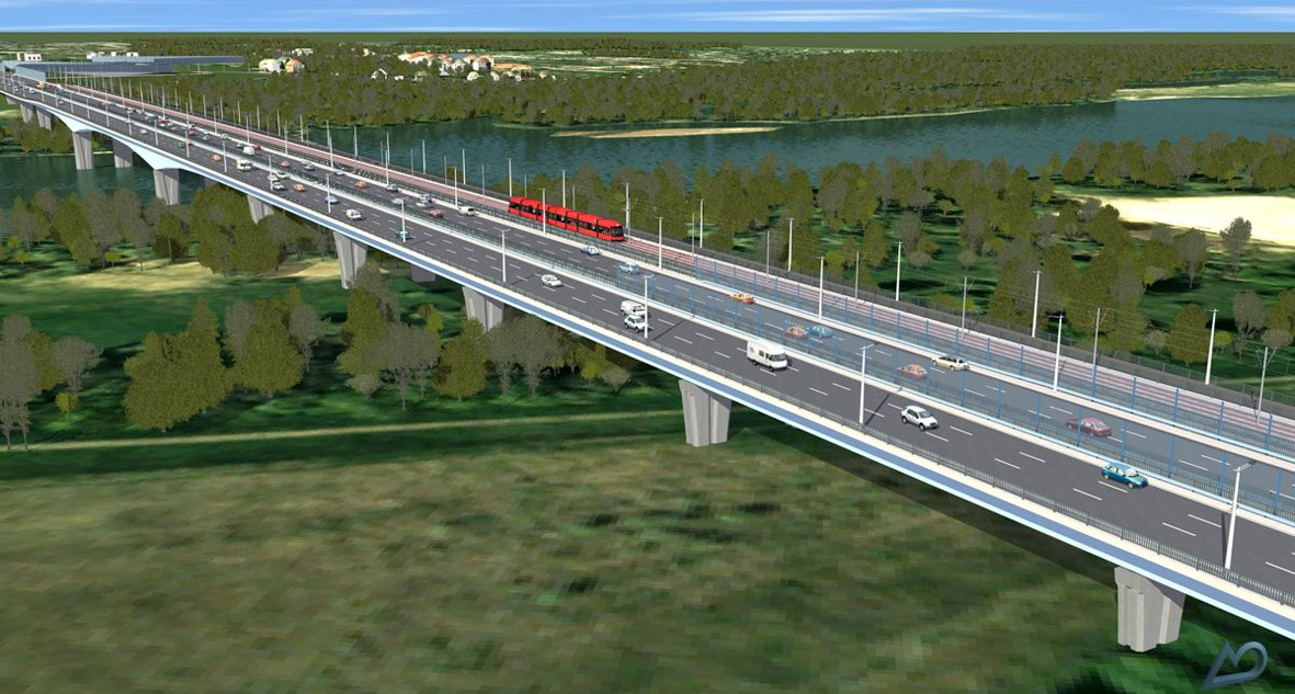
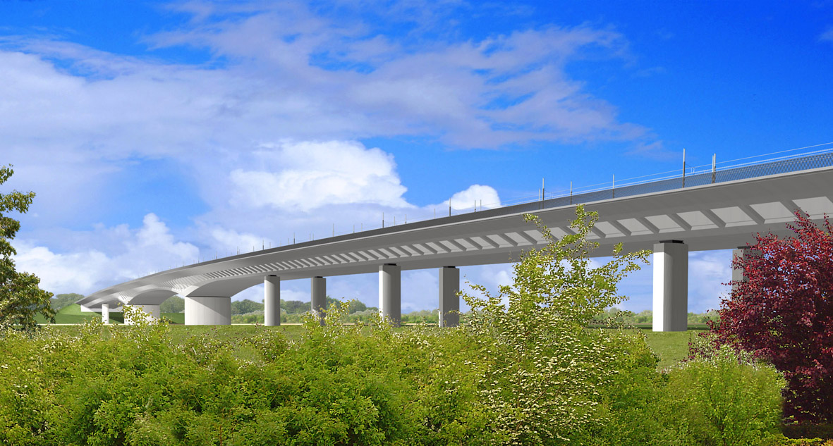
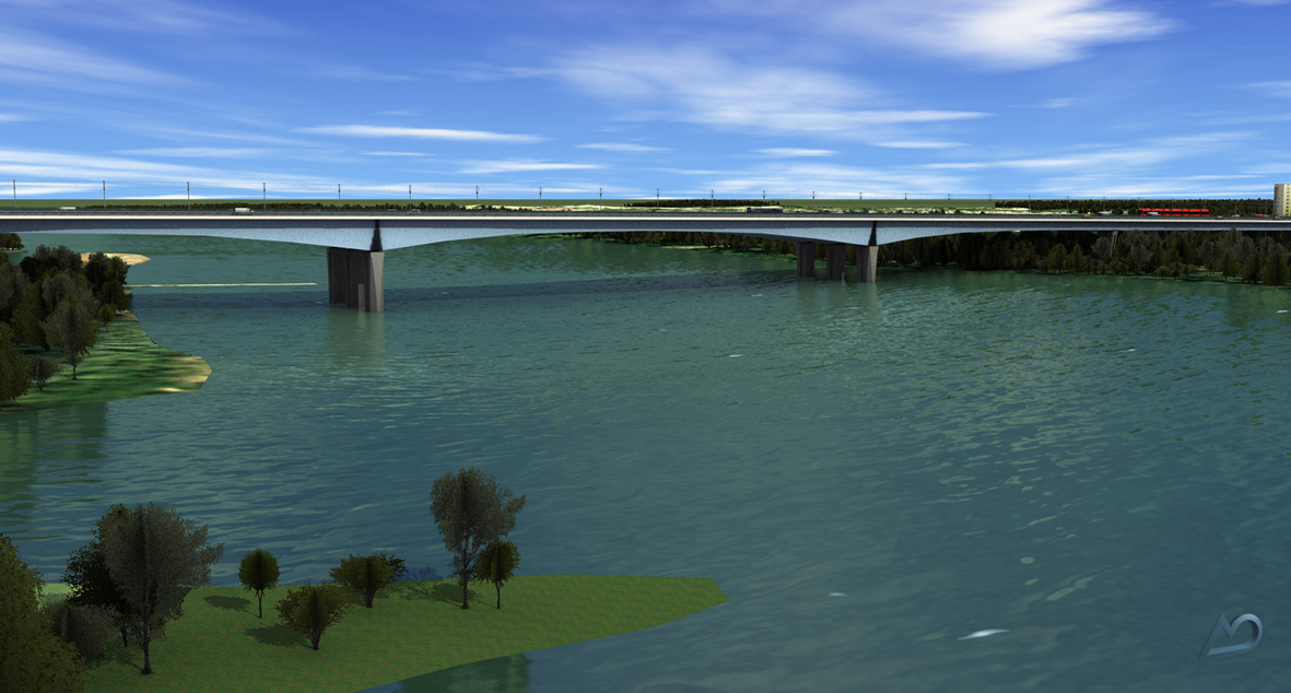
At its core, the solution comprises a 3.4km-long six-lane section of road, including the 800m-long bridge across the river. On top of that there is a 3.8km stretch of double-track tram line with a slab-track system. Three large intersections, at times towering three levels high, establish the links to the existing traffic routes. To the west, the tram is linked by a wye (railway triangle) and to the east the area required for an additional wye is being kept free. 820,000m³ of material has to be moved for the embankments.
The links to the access roads have to be redesigned and all entries and exits have to be re-established. Besides the river bridge, a further 11 bridges, 5 tunnels for the tram line as well as 19 retaining wall structures totalling approx. 2,500m are going to be built. Over 44,000m² of sound attenuation barriers are also part of the plan.


The links to the access roads have to be redesigned and all entries and exits have to be re-established. Besides the river bridge, a further 11 bridges, 5 tunnels for the tram line as well as 19 retaining wall structures totalling approx. 2,500m are going to be built. Over 44,000m² of sound attenuation barriers are also part of the plan.

Overlaps
The various mains pipes/wiring (gas, fresh water, sewerage, electricity etc.) provided a particular challenge due to the extremely restricted conditions posed by the densely built-up area surrounding the junction. This meant that crossing mains was unavoidable in the plans. Working with our local specialists, we could locate more than 800 potential overlaps which had to be taken into account during the planning process.
With Polish Fonts
The design was done with card_1; AutoCAD was used for the drawing editing and the engineering structures. The planning documents had to be annotated in Polish. So the Polish version of card_1 certainly came in handy. Converting the project data was never a problem. Also worth mentioning: the updated DXF interface provided an excellent tool to seamlessly exchange data with AutoCAD
Cross-sections
One of the most powerful features of card_1 which was extensively used for this project is the elaborate cross-section designer. The software perfectly models any parallel alignments or routes and performs technically sound calculations and transformations. Even combining different traffic systems, each with their different technical requirements, is no big challenge for card_1. This was absolutely essential for this project! Using the powerful programming language CardScript, it was no problem to calculate all corresponding cross-sections, including the bundles for the road and tram routes. Some of the cross-sections consisted of up to six lanes and a two track tram route. The real boost, however, is the script-based drawing generator used to create drawings with card_1, even more so if you are including reusable script snippets or dialog-based scripts. In no time at all and with the help of standardised chainage data, we were able to produce ready-to-deliver base maps, elevation plans and cross-section drawings. Thanks to the scripts, the internal commands as well as the various settings in the “card_1 user engine room” we could produce Polish drawings without the need for any further manual editing.

In Action
The surveying data was processed entirely with card_1. Digital terrain models were created and evaluated wherever necessary. The entire road and railway design including the drainage facilities were calculated with card_1. We were able to produce all the required data: e.g. setting-out data, base maps, utility, drainage, equipment and elevation plans as well as cross-section drawings. To round off the results we created surface models for video animations. Most of the base maps were created map-sheet-free in the topographic system, otherwise using global layers.