Sewer modules
Engineers, planners and local authorities use card_1 to calculate sewer networks based on hydraulic calculation methods. From the simple time coefficient method right through to the complex dynamic parallel step method, the proven calculation methods FLUT and DYNA are used as the calculation cores, depending on the application type (from initial development through to reconstruction).
The calculation fundamentals and the results can be clearly shown to engineering standards during the planning itself as well as in any presentations. You can create attractive longitudinal profiles, cross-sections and base maps or individually compiled tables on the basis of topographic data or scanned maps.
Sewer Data Import/Export
Import of sewer data from ISYBAU Format Typ K/EY and Im-/Export of sewer data in ISYBAU Format XML.
Sewer Network Hydraulics Time Coefficient Method
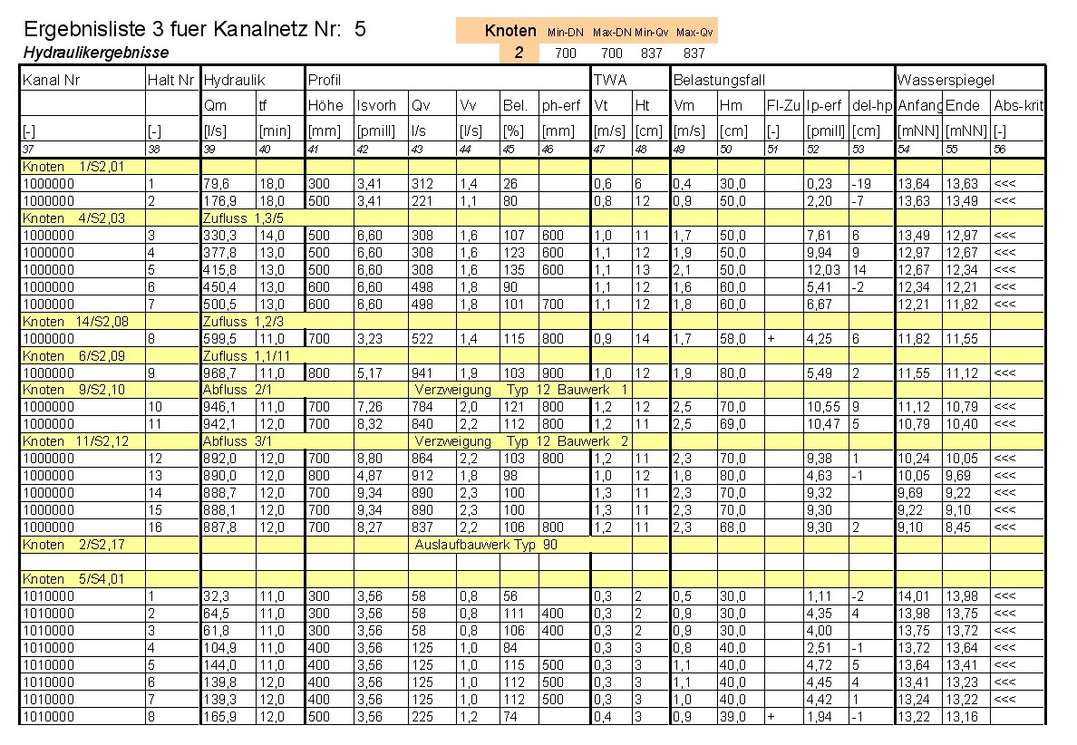
You can calculate and dimension sewer networks according to the time coefficient method for a maximum of 250 reaches. This method is used to dimension and conduct preliminary planning of "simple" networks.
You then define the rainfall frequency and use either block rainfalls according to Reinhold or create your own rain definitions, e.g. following the so-called KOSTRA-Atlas (coordinated regionalized heavy rainfall evaluations). more >
Sewer Network Hydraulics - Hydrological
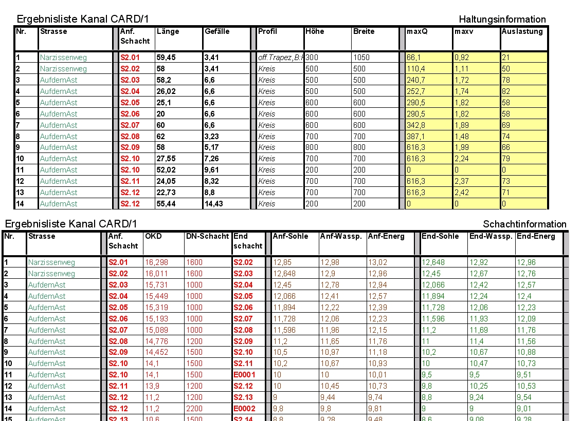
You can calculate and dimension sewer networks according to a hydrological calculation model. This model is suitable for 1,000, 2,000, 3,000 and more than 3,000 reaches.
The hydrological calculation model considers the entire run-off curve and determines its change on the surface and in the sewer network. Thus the actual sewer conditions are taken into account when dimensioning and calculating storm water tanks.
Sewer Network Hydraulics - Hydrodynamic

You can run a hydrodynamic verification calculation of sewer networks. This model is suitable for 1,000, 2,000, 3,000 and more than 3,000 reaches.
This complies with the European Norm EN 752 as well as with the ATV (German Association for the Water Environment) guideline A118 for larger networks or within areas with increased safety requests when using the hydrodynamic calculation method. They stipulate that flooded areas must be verified. Detailed knowledge about how a sewer network copes with submergence is provided by simultaneously calculating sewer cross-sections and special structures in one calculation step.
4D Sewer Level Simulation
Profile Drawing (Sewer)
You can create complete, technically-sound profile drawings in compliance with the existing guidelines with flexible annotations, sewers and other strings.
Sewer profile drawings may also be generated in reference to any existing road longitudinal profile. These drawing portions are displayed in the same manner with tangent strings, dimensions, drawing sheet borders and titleblocks in one drawing.
Sewer Base Map Drawing
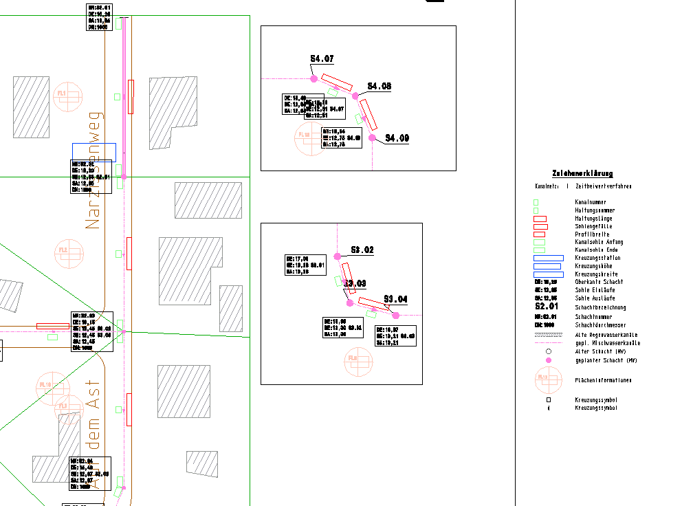
You can create complete, ready-to-deliver, technically-sound sewer base map drawings in compliance with the existing guidelines with flexible annotations. This module is especially useful when logging the existing conditions, for reconstruction works or when planning sewer networks as well as when planning road drainage systems.
Sewer base maps may be combined with any other technical drawings and displayed in the base map view.
